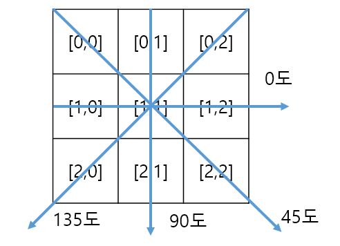
지문에서 ridge의 방향(orientation)은 gradient에 수직한 방향이다(그런데 벡터인 gradient와는 달리 ridge의 방향은 모호함이 있다. 시계방향 또는 반시계방향으로 90도 회전이 모두 동일한 ridge의 방향이다).  gradient의 방향각이 $\alpha$일 때 수직인 ridge의 방향각은 $\theta =\frac{\pi}{2} + \alpha$로 정의하자. 방향각을 주어진 gradient 성분 $\nabla I = (g_x, g_y)$로 표현하기 위해서

$$ \sin 2\alpha = 2 \sin \alpha \cos \alpha = 2 \frac{g_x}{\sqrt{g_x^2 + g_y^2}}\frac{g_y}{\sqrt{g_x^2 + g_y^2}}$$

$$\cos 2\alpha = \cos^2 \alpha - \sin^2\alpha = \frac{g_x^2}{g_x^2 + g_y^2} -\frac{g_y^2}{g_x^2 +g_y^2}$$ 

임을 이용하자. $$\tan 2\alpha = \frac{ 2g_x g_y}{ g_x^2 - g_y^2}$$로 쓸 수 있으므로 ridge의 방향각은

$$ \theta =\frac{\pi}{2} + \frac{1}{2} \arctan \frac{2g_x g_y}{g_x^2 - g_y^2}$$

임을 알 수 있다. $(g_x, g_y) \rightarrow (-g_x, -g_y)$이더라도 ridge의 방향은 동일하므로 $\theta$의 범위는 $0\le \theta < \pi$로 제한된다.


이미지의 한 지점에서 ridge의 방향은 그 점을 중심으로 하는 적당한 크기의 윈도 평균값으로 추정한다. gradient 성분은 Sobel 연산자나 Prewitt 연산자를 convolution해서 얻을 수 있다. 따라서 지문 이미지 상의 픽셀 좌표 $(i,j)$에서 ridge의 방향은

$$\theta_{ij} = \frac{\pi}{2} +\frac{1}{2}\arctan \frac{2 G_{xy}}{G_{xx} - G_{yy}}$$

$$ G_{xy} = \sum_{W} \text{gradX}_{ij} \times \text{gradY}_{ij}$$

$$ G_{xx} = \sum_{W} \text{gradX}_{ij} \times \text{gradX}_{ij}$$

$$ G_{yy} = \sum_{W} \text{gradY}_{ij} \times \text{gradY}_{ij}$$

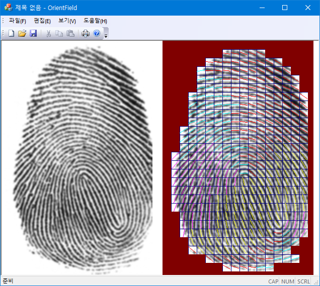
아래 결과는 5x5 크기의 Gaussian filter를 적용한 지문 이미지에 17x17 크기의 윈도를 겹치지 않게 잡아서 평균을 계산한 결과다. $G_{xx}+G_{yy}$가 최대값의 $20\%$보다 작은 영역은 방향을 표시하지 않았다 (red:0~45, yellow:45~90, magenta: 90~135, cyan: 135~180).

int RidgeOrientaion(BYTE *img, int w, int h, int bsz/*17*/, double *omap) {
    const int nn[] = {-w - 1, -w, -w + 1, -1, 0, 1, w - 1, w, w + 1};
    const int sobelX[] = {-1, 0, 1, -2, 0, 2, -1, 0, 1};
    const int sobelY[] = {-1, -2, -1, 0, 0, 0, 1, 2, 1};
    const int xmax = w - 1, ymax = h - 1;
    std::vector<int> gradx(w * h, 0);
    std::vector<int> grady(w * h, 0);
    for (int y = 1, pos = w; y < ymax; y++) {
        pos++; //x = 0;
        for (int x = 1; x < xmax; x++, pos++) {
            int sx = 0, sy = 0; 
            for (int k = 0; k < 9; k++) {
                int v = img[pos + nn[k]];
                sx += sobelX[k] * v;
                sy += sobelY[k] * v;
            }
            gradx[pos] = sx;
            grady[pos] = sy;
        }
        pos++; // x = xmax;
    }
    const int ny = h / bsz;
    const int nx = w / bsz;
    for (int iy = 0; iy < ny; iy++) {
        for (int ix = 0; ix < nx; ix++) {
            int sxy = 0, sxx = 0, syy = 0; 
            int pos = (iy * w + ix) * bsz; //starting position of block(ix, iy)
            int *dx = &gradx[pos];
            int *dy = &grady[pos];
            for (int jj = 0; jj < bsz; jj++) {
                for (int ii = 0; ii < bsz; ii++) {
                    int gx = dx[jj * w + ii];
                    int gy = dy[jj * w + ii];
                    sxy += gx * gy;
                    sxx += gx * gx;
                    syy += gy * gy;
                }
            }
            omap[iy * nx + ix] = 0.5 * (PI + atan2(double(2.0 * sxy), double(sxx - syy)));
        }
    }
    //...identify fingerprint regions and draw orientation map;
    return 1;
}
 
728x90

'Image Recognition' 카테고리의 다른 글

Edge Preserving Smoothing  (0) 2024.02.14
Watershed Segmentation  (0) 2021.02.27
Contrast Limited Adaptive Histogram Equalization (CLAHE)  (3) 2021.02.15
Fixed-Point Bicubic Interpolation  (1) 2021.01.19
Distance Transform  (0) 2021.01.16
Posted by helloktk
,

더보기
비교: Rosenfeld Algorithm(Graphics Gem IV)

Neighborhood Map;

[0 1 2]

[7 8 3]

[6 5 4]

int Thinning_2pass(BYTE *image, int w, int h) {
    const int xmax = w - 1, ymax = h - 1;
    const int nn[9] = {-w - 1,- w, -w + 1, 1, w + 1, w, w - 1, -1, 0};//clockwise;
    const BYTE FG = 255, BG = 0;
    bool *flag = new bool [w * h];
    int pass = 0, ok = 0;
    int nb[9];
    while (!ok) {
        ok = 1; pass = (pass + 1) % 2;
        for (int i = w * h; i-->0; ) flag[i] = false;
        for (int y = 1, pos = w; y < ymax; y++) {
            pos++;//x=0;
            for (int x = 1; x < xmax; x++, pos++) {
                if (image[pos] == FG) { //fg;
                    // condition 1; 
                    int count = 0;
                    for (int k = 0; k < 8; k++) 
                        if (image[pos + nn[k]] == FG) count++;
                    if (count >= 2 && count <= 6) {
                        for (int k = 0; k < 8; k++) nb[k] = image[pos + nn[k]];
                        nb[8] = nb[0]; //cyclic;
                        // condition 2;
                        int trans = 0;
                        for (int k = 0; k < 8; k++)
                            if (nb[k] == BG && nb[k + 1] == FG) trans++;
                        if (trans == 1) {
                            // condition3: top&&left=bg || bot=bg || right=bg
                            if (pass == 0 && (nb[3] == BG || nb[5] == BG ||	
                                (nb[1] == BG && nb[7] == BG))) {
                                    flag[pos] = true; ok = 0;
                            } else { // condition4: bot&&right=bg || top=bg || left=bg 
                                if (pass == 1 && (nb[1] == BG || nb[7] == BG ||	
                                    (nb[3] == BG && nb[5] == BG))) {
                                        flag[pos] = true; ok = 0;
                                }
                            }
                        }
                    }//(2<=count<=6);
                }
            }//for_x;
            pos++;//x = w - 1 skip;
        } //for_y;
        // remove flaged pixels;
        for (int y = 1, pos = w; y < ymax; y++) {
            pos++;//x = 0;
            for (int x = 1; x < xmax; x++, pos++) 
                if (flag[pos]) image[pos] = BG;
            pos++; //x=w-1;
        }
    }
    delete [] flag;
    return 1;
}


728x90

'Image Recognition > Fundamental' 카테고리의 다른 글

Insertion Sort  (0) 2021.02.24
Optimized Median Search  (0) 2021.02.24
Is Power of 2  (0) 2021.02.12
Flood-Fill and Connected Component Labeling  (2) 2021.02.10
Edge and Corner Detection  (0) 2021.01.27
Posted by helloktk
,

Edge를 보존하는 low-pass filter로 주어진 픽셀 값을 그 위치에서 edge 방향을 따라 구한 평균값으로 대체한다. 방향은 8방향 (45도) 기준이다. Edge의 방향은 그림처럼 중심 픽셀을 기준으로 주변의 8개를 픽셀을 이용해서 45도씩 회전하면서  차이(평균 변화율)를 계산하여 가장 작은 값을 주는 방향으로 잡는다. 중심 픽셀이 line[1][1]일 때

     0도 에지: abs(line[1][0] - line[1][2])가 최소

   45도 에지: abs(line[0][0] - line[2][2])가 최소

   90도 에지: abs(|ine[0][1] - line[2][1])가 최소

 135도 에지: abs(line[0][2] - line[2][0])가 최소 

Edge 방향의 3 픽셀 평균값으로 중심 픽셀 값을 대체하면 edge는 보존하면서 mean filter를 적용한 효과를 얻을 수 있다.


void smooth_ep_3x3(BYTE *src, int width, int height, BYTE* dst) {
    const int xend = width - 2, yend = height - 2;
    BYTE *line[3];
    line[0] = src; line[1] = line[0] + width; line[2] = line[1] + width;
    BYTE *dst_line = dst + width;        // starting dst row;
    for (int y = 0; y < yend; ++y) {
        for (int x = 0; x < xend; ++x) {
            int diff1 = line[1][x] - line[1][x + 2];
            if (diff1 < 0) diff1 = - diff1;
            int diff2 = line[0][x] - line[2][x + 2];
            if (diff2 < 0) diff2 = - diff2;
            int diff3 = line[0][x + 1] - line[2][x + 1];
            if (diff3 < 0) diff3 = - diff3;
            int diff4 = line[0][x + 2] - line[2][x];
            if (diff4 < 0) diff4 = - diff4;
            
            if (diff1 <= diff2 && diff1 <= diff3 && diff1 <= diff4)         //0-도
                dst_line[x + 1] = (line[1][x] + line[1][x + 1] + line[1][x + 2]) / 3;
            else if (diff2 <= diff3 && diff2 <= diff4)                      //45-도
                dst_line[x + 1] = (line[0][x] + line[1][x + 1] + line[2][x + 2]) / 3;
            else if (diff3 <= diff4)                                        //90-도;
                dst_line[x + 1] = (line[0][x + 1] + line[1][x + 1] + line[2][x + 1]) / 3;
            else                                                            //135-도;
                dst_line[x + 1] = (line[0][x + 2] + line[1][x + 1] + line[2][x]) / 3;
                
            dst_line += width;                              //move to next dst line;
        }
        // increases src line ptr;
        BYTE *tptr = line[2] + width;
        line[0] = line[1]; line[1] = line[2]; line[2] = tptr;
    }
};

9번 반복 적용 결과: 지문처럼 규칙적인 패턴이 나오는 경우는 Gabor 필터를 이용하면 보다 좋은 결과를 얻을 수 있다.

네이버 블로그 이전

iteration에 따른 correlation의 계산:

iter=0, corr w.r.t original=0.925144, corr w.r.t previous=0.925144
iter=1, corr w.r.t original=0.903661, corr w.r.t previous=0.985120
iter=2, corr w.r.t original=0.888224, corr w.r.t previous=0.994821
iter=3, corr w.r.t original=0.876582, corr w.r.t previous=0.997403
iter=4, corr w.r.t original=0.866254, corr w.r.t previous=0.998183
iter=5, corr w.r.t original=0.856620, corr w.r.t previous=0.998596
iter=6, corr w.r.t original=0.847365, corr w.r.t previous=0.998841
iter=7, corr w.r.t original=0.838400, corr w.r.t previous=0.998981
iter=8, corr w.r.t original=0.829703, corr w.r.t previous=0.999088

728x90

'Image Recognition' 카테고리의 다른 글

Distance Transform  (0) 2021.01.16
FFT 알고리즘의 재귀적 구현  (0) 2021.01.14
Octree Quantization  (0) 2021.01.12
Median-Cut 컬러 양자화  (0) 2021.01.12
Union-Find 알고리즘을 이용한 영역분할  (0) 2021.01.11
Posted by helloktk
,

물체의 형상은 폴리곤이나 폴리곤의 집합으로 근사적으로 표현할 수 있다. 예를 들면 snake나 active shape model (ASM) 등에서 손 모양이나 얼굴의 윤곽, 또는 의료 영상 등에서 장기의 모양 등을 표현할 때 사용이 된다. 이러한 응용에서 주어진 형상을 기준으로 주어진 형상에 정렬을 시켜야 필요가 생긴다. 일반적으로 카메라를 써서 얻은 각 영상에서 추출한 정보들 사이에는 서로 사영 변환의 관계로 연결된다. 그러나 많은 경우에는 in-plane 변형만 고려해도 충분할 때가 많다. 이 경우에 가장 일반적인 형상의 변형은 affine 변환으로 표현된다. 회전(rotation), 평행 이동(translation), 크기 변환(scale transformation) 그리고 층 밀림(shear)을 허용하는 변환이다. 물론, 간단한 경우로는 shear를 제외할 수도 있고 (similarity transformation), 더 간단하게는 크기 변환을 제외할 수도 있다 (isometric transformation).

$N$개의 꼭짓점을 갖는 두 개의 형상 $S=\{(x_1, y_1), (x_2, y_2),..., (x_N, y_N) \}$, $S'=\{(x'_1, y'_1), (x'_2, y'_2),..., (x'_N, y'_N) \}$이 affine 변환에 의해서 연결이 되는 경우에 각 꼭짓점 사이의 관계는

\begin{align} x'_i &= a x_i  + b y_i + t_x \\ y'_i &= c x_i + d y_i + t_y, \quad (i=1,2,..., N);\end{align}

의 6개의 매개변수$(a, b, c, d, t_x, t_y)$에 의해서 기술이 된다(평행 이동: $x/y$축 방향 2개, 회전: 1개, shear: 1개, 스케일: $x/y$축 방향 2개). Affine 변환에 의해서 평행인 두 직선은 변환 후에도 평행인 관계를 유지한다.

꼭짓점 위치는 실제로 다양한 영상처리 과정에 의해서 얻어지므로 필연적으로 노이즈를 포함하게 되어서 일종의 랜덤 변수로 생각해야 한다. 주어진 랜덤 변수에서 최적으로 매개변수를 추출하기 위해 최소자승법을 이용한다. Affine 변환된 좌표와 실제 측정된 좌표 사이의 거리 차이를 최소화하는 매개변수를 찾도록 하자:

$$L=\sum_i \big| x'_i - a x_i - b y_i - t_x \Big|^2 + \big| y'_i - c x_i -d y_i - t_y\big|^2 $$

Affine변환을 규정하는 매개변수를 구하기 위해서는 L을 각 매개변수에 대해서 미분해서 극값을 가질 조건을 구하면 된다:

        ∂L/∂a = -2 * ∑ (x'i - a * xi - b * yi - tx) * xi ;
        ∂L/∂b = -2 * ∑ (x'i - a * xi - b * yi - tx) * yi ;
        ∂L/∂c = -2 * ∑ (y'i - c * xi - d * yi - ty) * xi ;
        ∂L/∂d = -2 * ∑ (y'i - c * xi - d * yi - ty) * yi ; 
        ∂L/∂tx = -2 * ∑ (x'i - a * xi - b * yi - tx) ;
        ∂L/∂ty = -2 * ∑ (y'i - c * xi - d * yi - ty); 

각 식을 0으로 놓아서 얻어지는 연립방정식을 행렬식으로 다시 정리하면,

$$\left[\begin{array}{ccc} S_{xx} & S_{xy} & S_x \\ S_{xy} & S_{yy} & S_y \\ S_x & S_y & N \end{array}\right]\left[ \begin{array}{ll} a & c \\ b & d\\ t_x & t_y \end{array} \right] = \left[\begin{array}{cc} S_{xx'} & S_{x y'} \\ S_{y x'} & S_{yy'} \\ S_{x'} & S_{y'}\end{array} \right]$$

여기서,
\begin{align} & S_{xx}= ∑ x^2, ~S_{yy} = ∑ y^2, ~S_{xy} = ∑ xy, \\ &S_x = ∑ x, ~S_y = ∑ y, ~S_{x'} = ∑ x', ~S_{y'} = ∑ y' \\ & S_{xx'} = ∑ xx', ~S_{xy'} = ∑ xy', ~S_{yx'} =∑ yx' \end{align} 이다.

// dst = (A,T)src;
//  [u]  = [ A0 A1 ][x] + A4
//  [v]  = [ A2 A3 ][y] + A5
//
BOOL GetAffineParameter(POINT *srcPts, POINT *dstPts, int n, double AT[6]) {
    double Sx, Sy, Sxx, Sxy, Syy;
    double Su, Sv, Sxu, Sxv, Syu, Syv ;
    double A[9], invA[9] ;
    double det ;
    Sx = Sy = Sxx = Sxy = Syy = 0;
    Su = Sv = Sxu = Sxv = Syu = Syv = 0;
    for (int i = 0; i < n; i++) {
        double x = srcPts[i].x, y = srcPts[i].y ;
        double u = dstPts[i].x, v = dstPts[i].y ;
        Sx += x;        Sy += y ;
        Sxx += (x * x); Sxy += (x * y); Syy += (y * y);
        Su += u;        Sv += v ;
        Sxu += (x * u); Sxv += (x * v); Syu += (y * u); Syv += (y * v);
    }
    A[0] = Sxx; A[1] = Sxy; A[2] = Sx;
    A[3] = Sxy; A[4] = Syy; A[5] = Sy;
    A[6] = Sx ; A[7] = Sy ; A[8] = n ;
    det = (A[0]*(A[4]*A[8]-A[5]*A[7])-A[1]*(A[3]*A[8]-A[5]*A[6])+A[2]*(A[3]*A[7]-A[4]*A[6])) ;
    if (det != 0.) {
        det = 1. / det; 
        invA[0] = (A[4]*A[8] - A[5]*A[7]) * det;
        invA[1] = (A[2]*A[7] - A[1]*A[8]) * det;
        invA[2] = (A[1]*A[5] - A[2]*A[4]) * det;
        invA[3] = (A[5]*A[6] - A[3]*A[8]) * det;
        invA[4] = (A[0]*A[8] - A[2]*A[6]) * det;
        invA[5] = (A[2]*A[3] - A[0]*A[5]) * det;
        invA[6] = (A[3]*A[7] - A[4]*A[6]) * det;
        invA[7] = (A[1]*A[6] - A[0]*A[7]) * det;
        invA[8] = (A[0]*A[4] - A[1]*A[3]) * det;
    }
    else return FALSE;

    AT[0] = invA[0] * Sxu + invA[1] * Syu + invA[2] * Su;
    AT[1] = invA[3] * Sxu + invA[4] * Syu + invA[5] * Su;
    AT[4] = invA[6] * Sxu + invA[7] * Syu + invA[8] * Su;
    AT[2] = invA[0] * Sxv + invA[1] * Syv + invA[2] * Sv;
    AT[3] = invA[3] * Sxv + invA[4] * Syv + invA[5] * Sv;
    AT[5] = invA[6] * Sxv + invA[7] * Syv + invA[8] * Sv;
    return TRUE ;
};

아래의 그림은 지문에서 얻은 특징점을 가지고 변환을 한 것이다. 밑에 그림이 기준 template (붉은 점)이고 윗 그림은 이 기준  template와 입력된 지문의 특징점(노란 점+ 녹색점) 사이에 서로 메칭이 되는 특징점(노란색)을 찾고, 그것을 기준으로 두 지문 영상 간의 affine 파라미터를 찾아서 기준 template을 변환시킨 것이다. 이렇게 하면 새로 찾은 특징점 중에서 기준 template에 없는 특징점(녹색점)을 발견할 수 있고, 이 특징점을 기준 template에 추가하여서 좀 더 넓은 범위를 커버할 수 있는 template을 만들 수 있다. 물론 추가된 녹색점이 신뢰할 수 있는 것인가에 대한 판단을 하기 위해서는 추가적인 정보가 더 요구된다.


728x90

'Image Recognition' 카테고리의 다른 글

Image Morphing  (0) 2010.01.24
Fant's Algorithm  (0) 2010.01.22
Color Counting  (0) 2010.01.18
Isometric Transformation  (0) 2010.01.11
Active Shape Model (3)  (0) 2009.12.30
Posted by helloktk
,

Contour Tracing

Image Recognition 2008. 5. 22. 22:51

이진 영상에서 전경의 경계를 저장하는 함수다. 전경의 최외각을 8-방향 연결성을 체크하면서 추적하도록 설계되었다(chain code를 참조하면 된다). 전경의 두께가 1 픽셀이더라도 항상 닫힌 윤곽선을 형성하게 만들었다(다르게 행동하도록 바꿀 수 있다). 전경에 서로 연결되지 않은 blob가 여러 개 있는 경우도 쉽게 처리할 수 있게 출력은 벡터 컨테이너를 사용했다.

struct Cntr {
   int x, y ; //position;
   int idirn ;//chain-code;
   Cntr() {} 
   Cntr(int x_, int y_, int idirn_)  : x(x_), y(y_), idirn(idirn_){}
};
typedef std::vector<Cntr> CntrVector;
#define FGVAL   255
#define BGVAL   0
#define VISITED 33          /* pixel value on accepted contour */
int GetNextCntr (BYTE** image, int *x, int *y, int *idirn);

int ContourTrace (BYTE** image/*binary image(FGVAL,BGVAL)*/, int width, int height,
                 std::vector<CntrVector* > &CntList) {
    /* CAUTION:: one-pixel border should have BGVAL!!!!*/
    for (int x = width; x-->0;)  image[0][x] = image[height-1][x] = BGVAL;
    for (int y = height; y-->0;) image[y][0] = image[y][width-1] = BGVAL;
    
    for (int y = height-1; y-->1;) {
        for (int x = width-1; x-->1;) {
            if (image[y][x] == FGVAL && image[y][x - 1] == BGVAL) {
                CntrVector *pCntrVec = new CntrVector ;
                int idirn = 2;
                int xStart = x, yStart = y;
                pCntrVec->push_back(Cntr(x, y, idirn));
                do {
                    image[y][x] = VISITED;  /* set the default value to VISITED */
                    GetNextCntr (image, &x, &y, &idirn);
                    pCntrVec->push_back(Cntr(x, y, idirn));
                } while (!(x == xStart && y == yStart));
                CntList.push_back(pCntrVec);
            }
        }
    }
    return CntList.size();
};

/* 다음 픽셀을 검사. 체인 코드; */
int GetNextCntr (BYTE** image, int *x, int *y, int *idirn);


728x90

'Image Recognition' 카테고리의 다른 글

Gaussian Mixture Model  (2) 2008.06.07
Rasterizing Voronoi Diagram  (0) 2008.05.26
RANSAC Algorithm  (0) 2008.05.24
Gausssian Scale Space  (0) 2008.05.22
Watershed Algorithm 적용의 예  (2) 2008.05.21
Posted by helloktk
,